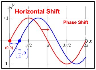
It is shown that Fourier sine and cosine transformations of truncated time domain signals which do not match the symmetry of the complete signal can produce a false dispersive susceptibility because they are equivalent to Kramers–Kronig inversion of finite bandwidth absorption data. The theory of phase-locked pulse pair techniques is reexamined, and it is concluded that linear experiments with phase-locked pulse pairs are completely equivalent to Fourier transform absorption spectroscopy and do not measure the refractive index or real part of the susceptibility. Experimental requirements for phase-resolved spectroscopy are outlined. Constant spectral phase shifts are demonstrated by diffracting pulses from a variable phase volume diffraction grating. Envelope time delays are generated by pathlength differences in an interferometer. It is demonstrated experimentally that a frequency domain measurement using spectral interferometry can simultaneously measure phase shifts with an accuracy of 0.1 rad (2σ) and time delays with a precision of 40 attoseconds (2σ) for 25 femtosecond optical pulses. Phase shifts and time delays are usually defined in terms of a carrier wave in magnetic resonance, but definitions based on the envelope of a single pulse are useful in optics. Let's wait to hear from him.Two different definitions of phase shifts and time delays are contrasted and shown to match different experimental methods of generating delayed pulses. Rest of any discussion is beside the point.

Number, though, not a function of frequency. 05 makes agreement between the digital filterĪnd its analog prototype very good. > order and normalized cut-off would be enough to calculate the phase shift vs. > this was normalized to the sample rate. > When the OP mentioned sample rate ("0.05"), since no units were given, I assumed Probably at least want to use Excel or some other tool for crunching the Probably there is a better way to do this directly in the z-domain, but I don't Order filters by first decomposing them to 1st/2nd order sections (factoring)Īnd then simply summing the phase responses. However, if you have that, you can work out the higher It was messy and ugly and what I came up with wasn't that general-only did 1stĪnd 2nd order filters. I also found I had toĭo some pre-warping correction for improved accuracy near the Nyquist frequency. Real/imaginary parts, take the arctan of imaginary/real). Past, when I've needed this, I've started with the s-domain transfer function,Īnd just worked it out with brute-force algebra (substitute s = jw, separate However, it is not a simple calculation, especially for higher orders. Order and normalized cut-off would be enough to calculate the phase shift vs. When the OP mentioned sample rate ("0.05"), since no units were given, I assumed > with the particular frequency in the passband, but also with the ratio > The phase performance of a digital Butterworth filter varies not only It's not just one number.Įngineering is the art of making what you want from things you can get. With the particular frequency in the passband, but also with the ratio The phase performance of a digital Butterworth filter varies not only > Butterworth Filter (Low Pass) with a cut-off frequency of 0.05 has a > However I need a function which gives me the phase delay of the filter > and have some great equations for calculating the coefficients as a


 0 kommentar(er)
